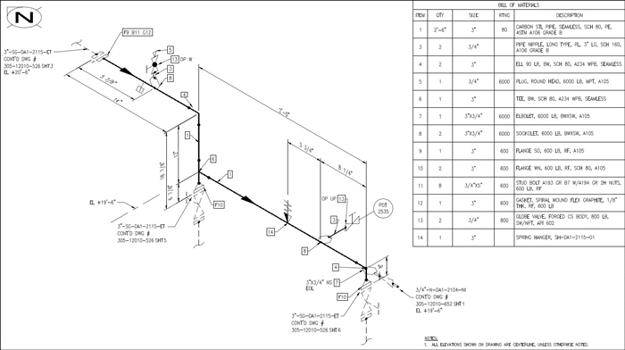
We´ll cover some of them to have an idea what each one represents and how affects the Isos. There are seven different isometric attachments. We don´t need to care about the properties of each component when generating the isos as all the information is already defined into them.

This means that the piping specification assigned to the pipework will define the 3D components considering dimensional and material properties for an intended service.

It´s a data-centric, piping specification driven solution fully integrated with SOLIDWORKS. It´s recommended that before continuing with this article you have a look to the article “ How to create piping isometric drawings with SOLIDWORKS” which explains in deeper detail how SolidPlant 3D generates them.Īs you may know SolidPlant 3D works on top of SOLIDWORKS Standard Edition. I will outline how to add different isometric attachments into a pipe line and how they are displayed into the piping isometric drawing. We can automatically create the piping isometric drawings for any pipe line or any selection in the graphic area in seconds.

SolidPlant 3D has embedded Isogen for the total automation of piping isometric drawings and eliminates the need to manually edit them which reduces fabrication and on-site construction errors. It allows us to edit the pipe lines at any stage in the design process and add comments, iso break points and others directly to the model in real time. Piping isometric attachments are properties or annotations we can add at any selected point or line in a 3D route assembly to be displayed into a piping isometric drawing.


 0 kommentar(er)
